Equatorial
Mount Tracking Errors
1, Sources of Mount Tracking Errors
For longer exposures it is necessary to use motor
driven equatorial mount. Telescope mounted on equatorial
mount is rotating in opposite direction of Earth
rotation, thus no trails should appear. The word SHOULD
is used intentionally, because there are several factors
which affect perfect tracking:
- The mount should be perfectly aligned
with Earth's polar axis. Any deviation of mount's
polar axis from Earth's axis causes tracking
errors.
- Even quality machined mount parts like worms,
worm gears, shafts are not absolutely perfect.
The parts are machined in micrometer precision at
best. We must realise that in astrophotography we
require tracking precison up to
arcseconds. That means, that e.g. teeth of teeth
on perimeter of wheel with diameter of 8cm must
be machined with accuracy of hundreeds of
nanometers!
As mount's shaft rotates, any error in its
surface and shape and also in worm and worm gear
surfaces and shapes causes a periodic bump in
tracking. The most observable is so called periodic
error of the mount which is caused by
inaccuracy of of worm. The period of this error
takes one revolution of gear (usually 5-10
minutes for common mounts).
More expensive mounts has possibility to suppress
this error by means of electronics - Periodic
Error Correction (PEC). The principle of PEC is
based on recording tracking corrections made by
observer by star tracking during one period. This
tracking corrections are then applied during
normal mount use.
- Atmospheric refraction causes
that stars are not moving exactly according to
their calculated trajectories.
- Further effects - tripod, scope,
focuser and other parts firmness, vibrations,
thermal changes agffect the result tracking
accuracy.
2, Mount Error Measuring
Mount errors can be simply measured by means of webcam.
Here is example of measuring my equatorial mount GEM1 (see
my scope) by means of K3CCDTools:
 |
Animated part of
screenshot (half size) of K3CCDTools
with Reticle ON. The scope was aimed to Vega
star (it was about 43° above horizon).
Capture resolution: 640x480
Scope: 8" F6 OrionOptics Europa Newtonian
Frame size (FOV): 10.27' x 7.70'
Seeing: windy, twinkling stars
"Capture Selected Frames" capture
mode was selected with period 1 second (exact
period was 1.11s).
I recorded 1321 frames (24min 35s) for further
analysis.
Note: Proper camera and scope must be set in
Options | Telescope and camera settings to obtain
correct results.
|
 |
I also recorded star's
trajectory with motor switched OFF. In this case
the star moves from west to east. It is necessary
for obtaining RA and DEC axes. The result
shows, that East-West axis is almost identical
with reticle's horizontal axis. The deviation is
6.02° (measured in K3CCDTools using mouse).
|
 |
I processed captured AVI file
with "If Lighter" method. It nicely
shows the "movement" of the star. The
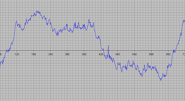
star trajectory reveals an error caused by bad
polar alignment (RA and DEC drifts) and also
periodic error.
|
Then I aligned frames according to Vega star (like if
I would want to stack frames for result picture of Vega).
When frames are aligned, then the shifts considering the
first frame contains data about RA and DEC drifts. Then I
used a new function - Export to Drift List (menu
Sequence Processing). At first the program asks for angle
of West axis (in my case it was 6.02°) and then it
exports data into text file.
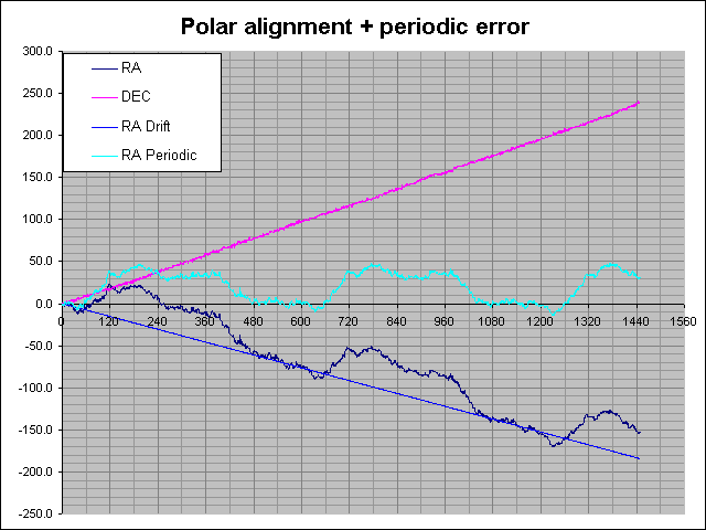
3, Mount Error Analysis
Then I imported data from the text file to Excel and
did the analysis:
4, RA Motor Speed Error Measurement
During my measurement of mount errors I noticed that
RA drift is usually to the East side, so I started to
suspect RA motor speed. That's why I did several
measurements of my RA axis drive. I measured the mount
with telescope loaded during day time.

Place mouse
pointer above image to see labels.
Click the image to see higher resolution image. |
The driving unit of my GEM1
consists of stepper motor and 2 brass wheels.
Both wheels have 31 teeths, so the gearing ratio
is 1:1. The second wheel drives the axis with
worm. At first I measured the period of my worm
axis. I stick a strip from electrical insulating
tape to the stepper motor wheel for better
reading wheel position.
The period was about 9min57s. Then I calculated
the number of teeths of the main RA axis teeth
wheel:
The Earth's sidereal day is:
sid_day = 23h56min04.09074sec = 86164.09074sec
Number of teeth = Round(sid_day / motor_period) =
Round(86164s/597s) = 144 teeth
|
 |
The measurement of a single period is rather
inaccurate, so I choose another method for
measuring.
I removed drive cover to better see brass wheels
and I signed one tooth of wheel with a pen. Then
I measured more periods of rotation to be more
precise. I also made use of my motor controller,
which have possibility to use 8X speed. The
factor 8 is accurate, because a binary counter is
used as frequence divider. Here are results of my
measurements:
| Number of period |
Measured time [min:sec] |
Worm wheel period [sec] |
| 12 |
14:55.47 |
596.980000 |
| 36 |
44:45.37 |
596.748889 |
| 48 |
59:40.32 |
596.720000 |
| 60 |
74:35.42 |
596.722667 |
Worm wheel period was calculated according to
the equation:
worm_period = 8* (time / number_of_periods)
The error caused by inaccurate read out the
brass wheel is maximum 5° (less than 1/2 tooth).
Error caused by a man reaction time could be +/-
0.3sec. So the result in 60 periods measuring
could be 5°/60=0.08333°= 1/4320 of period (i.e.
about 0.14sec). The reaction time error should
not affect result more than 8*0.3sec/60=0.04s.
If we exclude the first table row (probably
higher error) we can get average value:
worm_period = 596.7305sec (+/- 0.18sec)
It means that "mount's sidereal day"
is:
mount_sid_day = 596.7305sec *
144 = 85929.2sec
The period of accurate drive system should be:
accurate_worm_period = sid_day / 144 =
86164sec/144 = 598.3611sec
My measurements confirm my suspicions - RA
drive is faster than it should be. The
inaccuracy of drive speed is 0.273%, which is
rather high error. The maximum
inaccuracy of my measurement was 0.03% (=0.18/596.7305).
The crystal oscillator unit has much
higher accuracy, so my conclusion is, that
inproper crystal frequency or inproper division
ratio of binary counter were used.
|
Now we can calculate the drift in RA caused by
inaccurate RA drive speed. The speed of star at celestial
equator is:
accurate_speed = 360°/sid_day = 360°/86164sec
= 0.0041781°/sec = 15.0411 arcsec/sec
The speed of telescope:
scope_speed = 360°/moun_sid_day =
360°/85929.2sec = 0.0041895°/sec = 15.0822
arcsec/sec
The star on equator is moving in telescope by speed
which is equal to difference of above speeds:
scope_star_drift = 15.0822arcsec/sec
- 15.0411arcsec/sec = 0.0411 arcsec/sec
= 2.466arcsec/min
My measurements showed me, that my mount has also (apart
from periodic error) constant drift in RA, which is ~2.5arcsec
per minute.
Back to AstroPhotography page
Computer generated images,
real images, drawings and texts are property of the
author and may not be reproduced or used without
permission of author.

Last Update:
07.10.2002
|