| K3's AstroPhotography | |
| "When I consider your heavens, the work of your fingers, the moon and the stars which You have set in place, what is Man that You are mindful of him?" -- Psalm 8:3,4 |
|---|
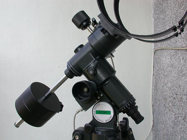
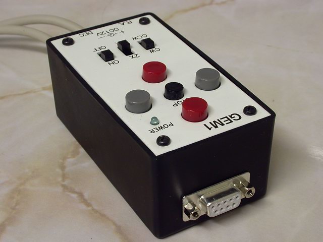
| Modification
of GEM1 for Computer Control As my GEM1 equatorial mount has rather high periodic error, I decided to do something with it. The most walkable way for me it was to modify GEM1 controller unit and add homemade Control Interface Unit into the GEM1 controller box. !WARNING! You can use the following
information on your own risk. Author is not responsible
for any damage of GEM1 controller or computer equipment.
The following procedure was done successfully by author,
but he cannot guarantee, that your modification will be
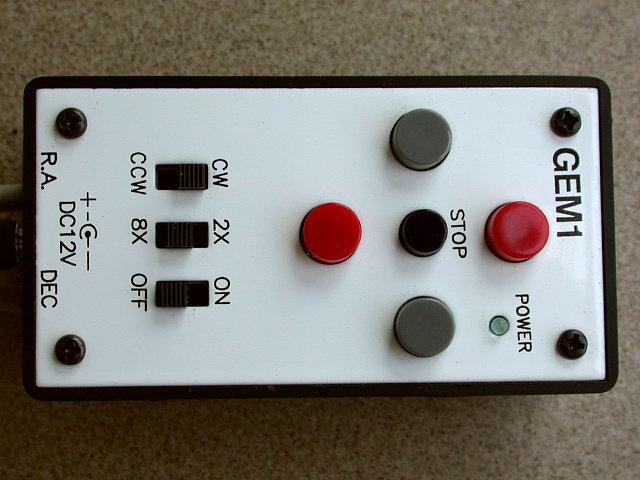
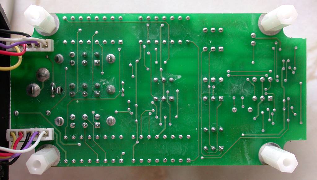
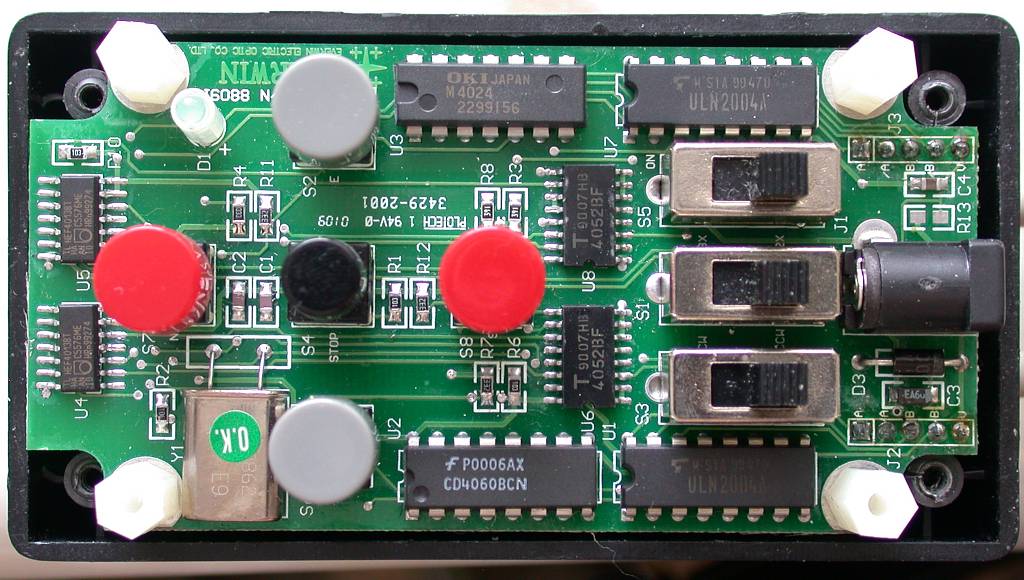
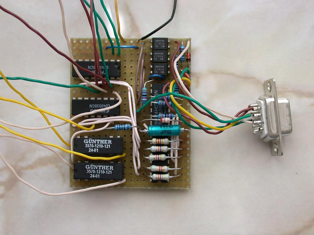
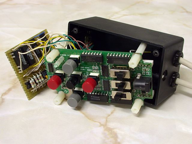
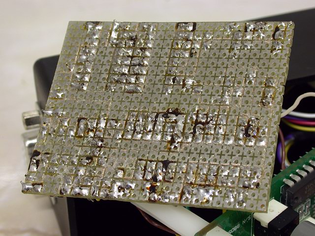
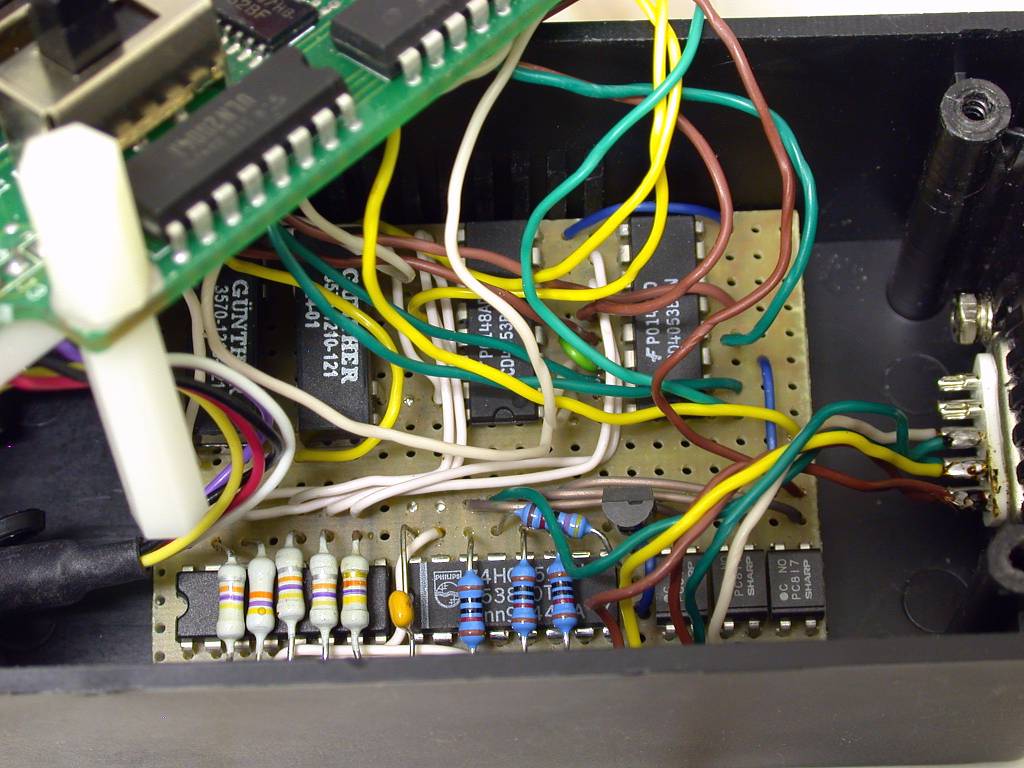
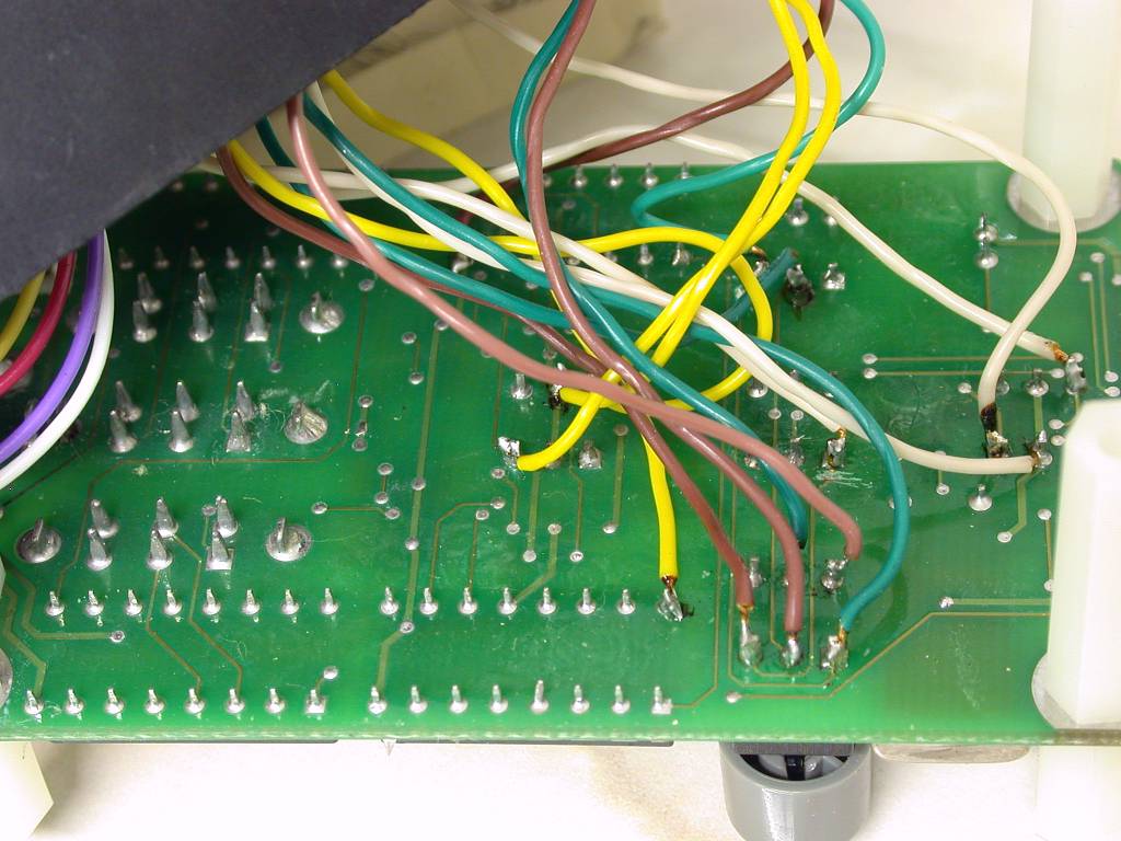
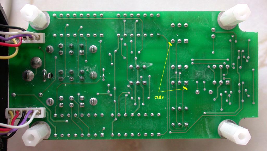
successful. Basically, Control Interface Unit (CIU) is an electronic switch equipped with computer interface for serial port. The electronic switches are connected to original mechanical switches. There was necessary to do two cuts of original PCB paths (see detail picture below). The electronic switches consists of CMOS switches and 2 relays (the DEC pushbuttons switch also motor drive current - about 150mA). The original GEM1 control unit still remains fully functional also without using computer. The CIU is realised on 50mm x 62.5mm stripboard. The principle of
operation Click the photos to see detailed images.
Programming the interface The control byte sent via serial port is defined by the table:
The modified GEM1 controller enables telescope
guiding, PEC and simple GOTO, now. The CIU is controlled
by means of K3CCDTools.
Click the picture to see full sized screen capture. Very similar interface is used in PISCO project. You can also find description of programming interface with 74HCT595, there. The page is still under construction. New informations are continually filled up. See Tests and Analyses of Homemade GEM1 Guiding System See Homemade GEM1 Autoguiding Setup Back to Equatorial Mount Tracking Errors page Back to AstroPhotography page Computer generated images, real images, drawings and texts are property of the author and may not be reproduced or used without permission of author.
Last Update: 06.10.2002 |